Internals
The below pictures show the Tavor dismantled. The only parts not taken apart are the safety and the butt assembly.
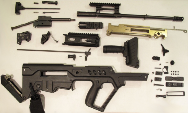
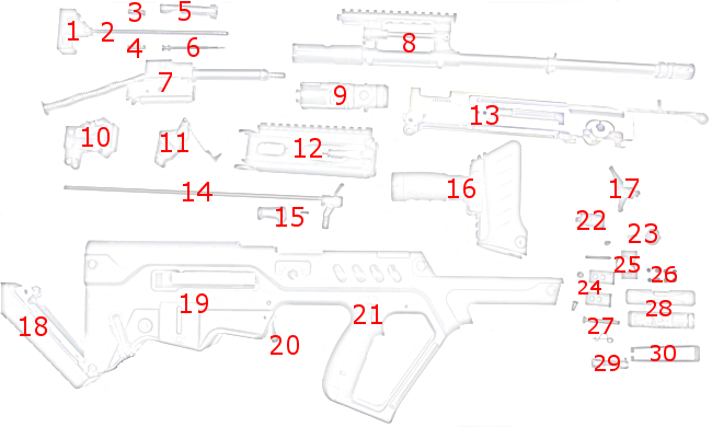
| 1 Buffer | 16 Grip, rail, folding grip |
| 2 Bolt carrier guide rod | 17 Super Sabra Lightning Bow Trigger |
| 3 Bolt guide pin | 18 Butt assembly |
| 4 Firing pin spring | 19 Receiver |
| 5 Bolt (left handed) | 20 Magazine release lever |
| 6 Firing pin | 21 Safety assembly |
| 7 Bolt carrier assembly, piston, return spring | 22 Deflector |
| 8 Barrel, flash suppressor, sight base | 23 Forward sling lock |
| 9 Gas cylinder assembly | 24 Ejection port shield |
| 10 Super Sabra Trigger Pack | 25 Front shield |
| 11 Bolt carrier stopper | 26 Ejection port shield screews |
| 12 Cocking handle guide, sight stabilizer sleeve, front sight | 27 Forward sling sleeve |
| 13 Receiver insert and trigger bar | 28 Ejection port cover and base |
| 14 Cocking handle bar | 29 Barrel locking pin |
| 15 Cocking handle, pin | 30 Extractor port shield |
Note that if you replace the OEM spring with another one (ex. Super Sabra Lightning Bow Trigger Steel Black), this spring is not required anymore. Do not waste time trying to figure out where it should go (ask me how I know!).
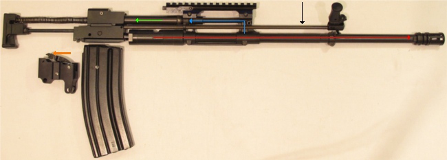
When a round is fired (red arrow), gas is vented through the gas port (blue arrow). The gas pushes on the gas piston (green arrow). The recoil assembly moves backwards, extracting and ejecting the spent cassing. It will also push the hammer back to reset it for the next shot.
You can also see the cocking handle bar (indicated by the black arrow) which pushes on the recoiling assembly that is used to cock the rifle.
Last detail, the original IWI mag is pinned to allow only 5 rounds, to respect Canadian laws.
This next picture shows how the parts fit in the insert. The insert ensures solid positionning of the barrel, magazine, recoil assembly and trigger assembly. It also provides tracks along which the recoil assembly moves back and forth. The receiver being plastic, the required tight tolerances would not last long without the metal insert.
The only part that is not held by the insert is the trigger.
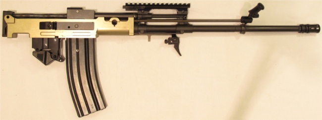
The trigger bar, colored in red in the below picture, moves forward when the trigger is pulled. The pivot point of the trigger is a pin, attached to the receiver. The bar pulls the sear activator forward, which releases the hammer.
See the page How-to remove the trigger mechanism spring for more information.
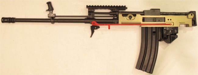
The safety blocks the trigger bar from moving forward. It pivots and blocks the bar where the red arrow points.

In these pictures, the recoil assembly is not fully in battery. The buffer rests inside the butt assembly, which pushes on the recoil spring and pushes the entire assembly forward. Since the receiver is absent, the assembly is not pushed enough.